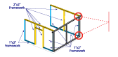
A. Assembling the Front Wall
To determine the height of your front wall, allow a ½” per foot slope between the front wall height and the back wall height to account for drainage.
Once a front wall height is determined you can determine the amount of 2” x 3” framework needed by upright posts by a maximum of 5” per post.
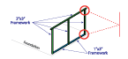
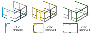
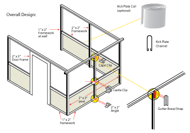
Build a 1” x 2” framework for the base, and a 2” x 3” framework for the headers.
For corner posts, add 1” to the headers for a 6” overhang on either side of the post.
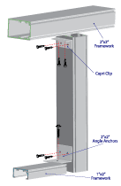
Lay the framework pieces on the ground with the spline grooves facing outward. Secure an angle anchor at the 1” x 2” intersection of the upright post and the base framework with the ¼” x 2 ¼” quickset anchors.
Attach the angle anchor to the upright post using the 8 x 9/16” self-drilling screws.
Using the capri clips and the 8 x 9/16” self-drilling screws secure the 2 x 3 header and the 2 x 3 upright post at the abutting angles.
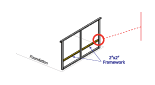
Use the ¼” x 2 ¼”quickset anchors to secure the wall to the foundation. Secure them 6” from each vertical post then every 24”.
B. Assembling and Connecting Side Walls
Determine the number of 2” x 2” framework needed for the center upright based on a maximum of 5” between posts and a 2” x 2” framework for the header.
Also needed are 1” x 2” framework for the base and front and back support posts.
Remember: Since the front and back walls are angled for a slope, the side wall should be at an angle as well to allow for this slope.
To ensure the proper angle, attach the 1” x 2” for the back wall and front wall to the 1” x 2” framework base.
Cut the 2” x 2” header to fit between the house and the front wall.
Using the 2” x 2” header as a guide, place the 2” x 2” header upright post and scribe all upright to match the slope, make sure the spline grooves face outward before assembly.
B.1 Connecting the Walls to the House
For masonry walls: pre-drill with a 3/16” drillbit through the 1” x 2” framework and into the house every 24”. Secure the framework to the house with the ¼” x 2 ¼” quickset anchors.
For wood walls: Pre-drill with the 5/64” drillbit through the 1” x 2” framework and into the house every 24”. Secure the framework to the house with the 10” x 3” hex-head screws.
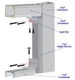
At the intersection of the upright post and the base framework, secure an angle anchor through the 1” x 2” framework into the foundation with the ¼” by 2 ¼” quickset anchors, then attach the angle anchor to the 1” x 2” front upright post using the 10” x 2” sheet metal screws, and the back upright post with the 8” x 9/16” self-drilling screws, attach the angle anchor to the 2” x 2” upright post using the 8” x 9/6” self-drilling screws.
Using the capri clips and the 8” x 9/16” self-drilling screws, secure the 2” x 2” header and the upright posts at the abutting angles.
Secure the wall to the foundation using the ¼” x 2 ¼” quickset anchors at 6” intervals from each vertical post, then every 24”.
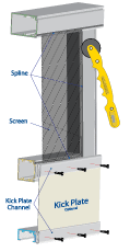
C. Using Kickplate (Optional)
To include a kickplate, attach a 2” x 2” rail 12” from the foundation using a castle clip.
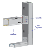
Secure the clip to the 2” x 3” upright with four (4) 8” x 9/16” self- drilling screws.
See section G for kickplate coil installation.


 Circular saw with plywood blade or hacksaw, variable speed drill, 4’ level, safety goggles, rollerknife, caulking gun, clear silicone caulking, tape measure, utility knife or tin snips.
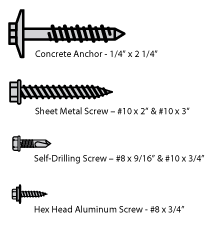 Concrete Anchor ¼ x 2 ¼ (holds all 1 x 2 framework to foundation and walls), sheet metal screw #10 x 2” and # 10 x 3” (used to attach the 1” x 2” framework to 2” x 3” post), self-drilling screw #8 x 9 1/16” and 10 x ¾” (used to attach all clips and framework bracing), hex head aluminum screw #8 x 3/4” (used to fashion roof panels to support wall).
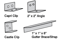 Capri clip (connects side framework to top framework), 2” x 2” angle (connects base and side framework), Castle clip (connects 2” x 2” rail to vertical framework), 1” x 1” x 6” angle (gutter brace/strap, connects gutter to vertical framework).
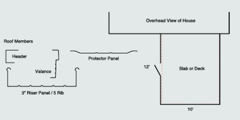
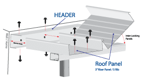 Run two(2) beads of caulk around the back of the wall header where your wall meets your home, then use roof pans 12” or longer than the roof opening to allow for overhang and proper drainage. Panels will slide easily into position, creating a snug fit.
Insert roof pan to curved lip edge and rotate down. Install one roof panel at a time as they interlock with each other.
Apply screws every 12” along the edge (length) where each panel interlocks with the one next to it. As you install each roof pan, apply caulking to each screw head to seal.
Run two(2) beads of caulk around the back of the wall header where your wall meets your home, then use roof pans 12” or longer than the roof opening to allow for overhang and proper drainage. Panels will slide easily into position, creating a snug fit.
Insert roof pan to curved lip edge and rotate down. Install one roof panel at a time as they interlock with each other.
Apply screws every 12” along the edge (length) where each panel interlocks with the one next to it. As you install each roof pan, apply caulking to each screw head to seal.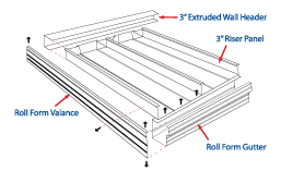 Optional protector panels can be installed at the same time as the above and foam installation can be installed inside the roof pan before covering with protector panel. Attach screws to beams at sides (every foot) and at the ends of the roof framing (two {2} per pan).